-
PDF
- Split View
-
Views
-
Cite
Cite
Nguyen Thai Cong, Pham Hoai Nam, Hoang Viet, Anand Marya, Digitally planned surgical crown lengthening: a novel bone reduction strategy to correct a gummy smile, Journal of Surgical Case Reports, Volume 2024, Issue 4, April 2024, rjae202, https://doi.org/10.1093/jscr/rjae202
Close - Share Icon Share
Abstract
This report describes the bone reduction guide which was digitally obtained to improve diagnosis, treatment outcome and follow-up. Treatment of gingival smiles due to altered passive eruption should include interdisciplinary planning and smile design to facilitate the prediction of treatment outcome. Crown lengthening surgery can be supported by digital tools to improve surgical planning and follow-up. A 30-year-old female patient was referred to a private dental clinic seeking solutions for her gingival smile. Based on the anatomical crown length, a smile design was created, and the patient was presented with a simulated smile before treatment. In the surgical phase, a full-thickness flap was raised in the upper jaw to achieve the desired outcome. Using cone-beam computed tomography to determine cementoenamel junction for smile design and treatment planning brings many benefits. Patients and clinicians can foresee treatment results. From there, appropriate changes can be made. The bone reduction guide is designed to rest on the bone to help the clinician cut the bone accurately and thoroughly follow the established plan.
Introduction
Crown lengthening is a frequently performed dental procedure, serving both aesthetic and functional purposes. It is employed to enhance visual aesthetics in cases of gingival smile correction and to expose healthy tooth structure beneath the gum for restorative purposes. The success of dental crown lengthening relies heavily on precise planning and execution, particularly during osseous resection. Inaccurate adjustments may result in suboptimal aesthetic outcomes or hinder the prosthetic restoration process.
Traditional approaches to dental crown lengthening heavily depend on the clinician’s visual assessment and involve osseous resection ~3–4 mm from the prospective gingival margin to recreate the biologic width [1–3]. This method relies on manual measurements and the surgeon’s expertise. In recent years, the field of dentistry has experienced transformative advancements through imaging technology and computer-aided design (CAD), providing new dimensions to treatment planning and execution, and 3D-printed ‘double guide’ stents have emerged, enabling clinicians to simultaneously reduce the gingiva and bone according to the treatment plan [4]. However, these guides are tooth and gingiva-supported, resulting in a distinct gap between the guide and the bone. This gap, coupled with the angle of the drill, may compromise precision during bone cutting.
This article introduces, for the first time, a novel design method for guiding bone cutting in dental crown lengthening procedures. It incorporates digital smile design to facilitate communication with the patient and plan crown lengthening treatment based on the smile design.
Patient case
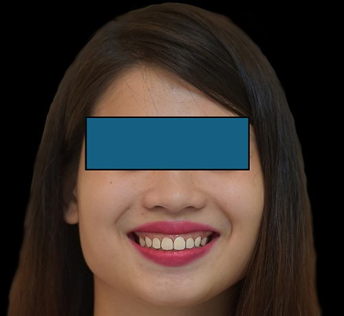
A 30-year-old female patient was referred to a private dental clinic seeking solutions for her gingival smile. The initial assessment encompassed a thorough clinical examination, photographic documentation, cone-beam computed tomography (CBCT) scans and impressions to collect essential data (see Fig. 1).
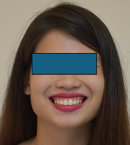
The length of the tooth crowns was clinically measured on the dental model (see Fig. 2), whereas the anatomical length was evaluated through CBCT images (see Figs 3 and 4). Based on the anatomical crown length, a smile design was created, and the patient was presented with a simulated smile before treatment (Figs 5 and 6). Upon approval of the simulated smile, a treatment plan was devised, establishing the future bone margin at 3-mm apical to the cementoenamel junction (CEJ) for each tooth, as indicated in Fig. 7.
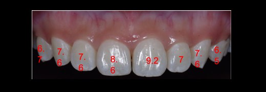
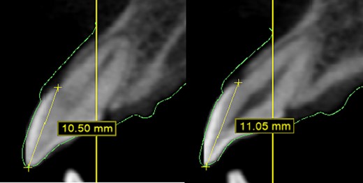
In CBCT, determine the CEJ of each tooth to ascertain the anatomical crown length.
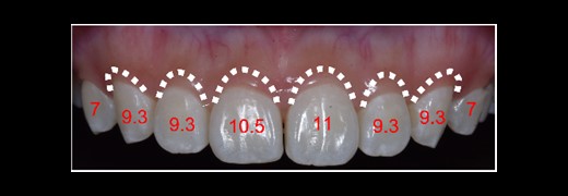
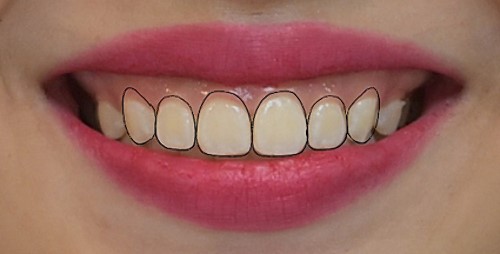
DSD with the anticipated gingival margin determined by the CEJ location.
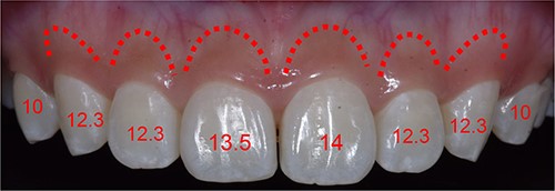
Simulating the position of the proposed bone margin 3 mm apical to the anticipated gingival margin.
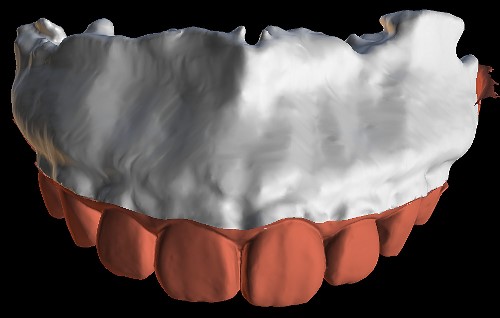
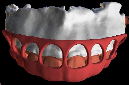
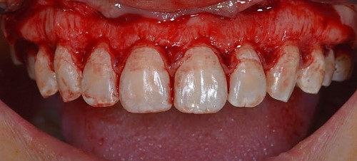
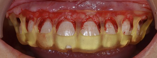
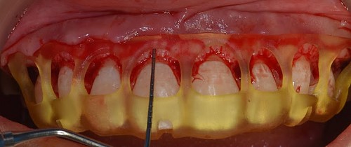
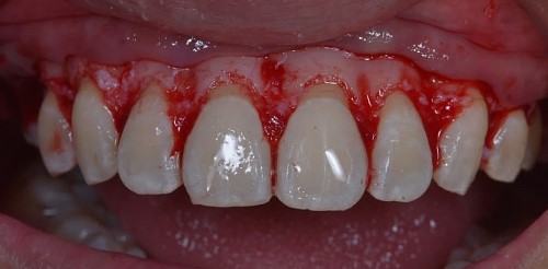
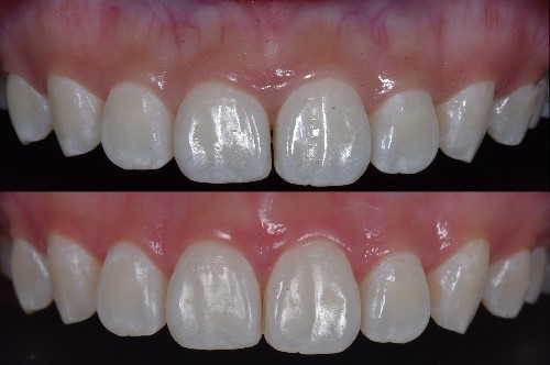
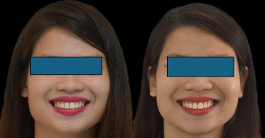
The STL files of the maxilla and teeth were manipulated using BlueSky Plan software (see Fig. 8). Subsequently, a guide was designed to facilitate osseous resection, adapting to both the teeth and the maxilla (see Fig. 9). In the surgical phase, a full-thickness flap was raised in the upper jaw, and the guide was affixed (see Figs 10 and 11). The guide snugly conformed to the bone, and its position was verified with a margin distance from CEJ set at 3 mm (see Figs 12 and 13). Postoperative results at 2 and 12 months are shown in Figs 14 and 15. The final outcomes closely resembled the Digital Smile Design (DSD) simulation conducted before treatment (see Fig. 16).

Discussion
The success of dental crown lengthening surgery relies on the precise adjustment of the bone position in alignment with the treatment plan [3]. CBCT measurements during treatment planning empower clinicians to anticipate outcomes. The osseous resection guide serves as a crucial tool for accurately adjusting the bone, translating the treatment plan into reality. In this case, the patient sought correction of a gingival smile without the need for prosthetic restoration. Therefore, it was imperative to ensure that the future gum margin did not exceed the CEJ. Determining the CEJ before treatment planning, particularly in cases where the bone margin is close to the CEJ, is not always achievable through clinical assessment alone. In this case, it was also very important to consider the altered passive eruption as this was a shorter clinical crowns. On utilizing the classification by Coslet et al., this case was classified as a 2B type case which requires an apically positioned flap along with osseous surgery for correction of the condition [5–8]. CBCT-based CEJ determination is essential in conjunction with the clinical altered passive eruption classification, and the future smile design should be adjusted accordingly [9].
Coachman et al. [10] highlighted the advantages of smile design based on CBCT compared with older methods; however, their bone grinding guide still relied on the gingival height rather than the bone. A similar approach was outlined by Pedrinaci et al. [11–13], where the bone grinding guide rested on the gingiva, creating a specific gap with the bone after a full-thickness flap was raised. This gap could compromise the clinician’s perspective and drill angle, leading to imprecise bone grinding results [14]. Alternatively, clinicians might need to remeasure each tooth after grinding, diminishing the efficacy of the bone grinding guide.
Conclusion
Utilizing CBCT to determine CEJ for smile design and treatment planning offers numerous advantages. Patients and clinicians can anticipate treatment results, allowing for necessary adjustments. The bone reduction guide is designed to rest on the bone, aiding the clinician in accurately cutting the bone and thoroughly following the established plan.
Clinical and surgical implications
The use of digital tools allows the clinician to plan according to smile aesthetics with proper communication with the team and patient, leading to more predictable, and less invasive surgical technique and increasing patient comfort.
Conflict of interest statement
The authors declare no conflict of interest.
Funding
None declared.
Patient consent
Informed consent was obtained from the patient for use of the images for academic and research purposes.
Informed consent
Written patient consent was obtained from the patient for use of her extra-oral and intra-oral records for academic and research purposes.


